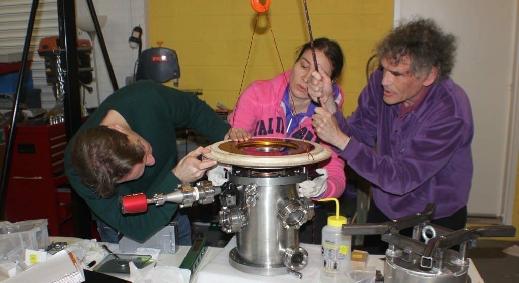
The new tungsten monolithic cathode, key to LPPFusion’s next set of experiments, arrived at our laboratory in Middlesex, NJ on Feb. 27. Careful acceptance tests confirmed that it is 99.95% pure tungsten and is within the 150 micron tolerances that we specified, a significant accomplishment by the manufacturer Tungsten Heavy Powder and their colleagues in Beijing where the tungsten factory is located. To manipulate the 35-kg cathode, LPPF’s research team erected a gantry, which they used to lift the tungsten cathode, protected by a steel “hat”, out of its box. (see video)
An independent laboratory report, which arrived almost simultaneously with the cathode, showed that the tungsten failed under a tension of only 4,000 psi (pounds per square inch), far less than the anticipated tensile strength of around 40,000 psi. The test was based on testing samples cut from a tungsten cathode blank produced in the same way as the tungsten cathode. The reason for the low strength is that the height of the tungsten cathode made it impossible for the manufacturer to fully compress the powder into a seamless piece of metal. The density of the cathode is 18.3 gm/cc, while a fully compressed tungsten part will have a density of 19.3 gm/cc. LPPFusion was aware of this difference in density, but did not expect it would result in such a low tensile strength.

The tensile strength —the strength for slow, long acting forces—has a considerable effect on how the tungsten cathode is to be attached to the steel plate that hooks it into the circuit and to the vacuum chamber that hangs beneath it. Thus the original plan for using the thin tungsten rim to attach the cathode to the steel plate was no longer workable as the rim was simply too weak to withstand the stress applied once the assembly was completed. Chief Scientist Lerner made an error in not concluding from the laboratory tests that the assembly would fail, an error not caught by other team members. So after the cathode was attached to the steel plate in an assembly, a gradual fracture of the supporting tungsten rim took place overnight, starting with localized weak points on the rim.

The rim served both the mechanical function of attaching the cathode to the steel plate and the electrical function of connecting the cathode to the current to be carried in the steel plate. However, the inner electrical current contact was on the innermost, unbroken part of the rim and remained functional. But cracks were identified that, if allowed to grow, could compromise that vital function.
Mechanical Engineer Tony Ellis succeeded in quickly proposing a replacement attachment method. In place of the tungsten rim, he designed a steel brace fit over the outer flange of the cathode to attach it to the steel plate. A high strength resin will fill the small space between the brace and the cathode flange. In this way, the force needed to press the tungsten and steel pieces together will be spread over the 1-inch-thick tungsten flange, not the 1/4-inch-thick rim.
To stabilize the edge of the tungsten bottom of the cathode, and to prevent any further microcracks, Rudy Frisch, an engineer and member of the LPPFusion Advisory Board, designed a fiber reinforced composite whose nylon fibers will be wound around the tungsten to compress it, while epoxy resin will be used to stabilize the fibers. Such fiber composites are widely used in the aerospace and other industries as high strength materials. The new brace (Figure 3) design was implemented by LPPFusion’s other Mechanical Engineer, Jonathan Klabacha and is now being manufactured. As the brace is made of steel and is a simple design, we expect it to be ready soon enough for assembly to be complete in April and firing of FF-1 to commence then.

To further minimize stress on the tungsten cathode, the team is minimizing the pressure needed to form a low resistance connection between the steel plate and the tungsten. For this connection, indium, a very soft metal, is squeezed between the two parts. LPPFusion’s CIO Ivy Karamitsos, who pitches in at the lab for fine-scale work, was able to reduce this pressure considerably with an improved indium application technique. Equally important, tests by Karamitsos and Lerner showed that the new technique insured that any microcracks in the tungsten current contacts can be successfully bridged over by the indium and will not cause problems during shots.
“We are confident that, despite the problems we’ve encountered, we will still be able to fire FF-1 with the tungsten electrodes,” says Lerner. “In any experimental program, errors will occur, but we can deal with them.”
To minimize future errors when experimenting with the newly designed FF-1 components, the team has added new quality assurance procedures. In particular, a “checker” will be designated at all design development points and during assembly, to question decisions about device assembly before they are implemented.
The good news is, the low tensile strength will not affect the cathode’s ability to stand up to the shocks it receives when FF-1 fires. Since the shot current and the magnetic fields it generates last only microseconds, the stress on the tungsten appears as an impact. The critical strength to resist impact is the fracture energy, and for a crack to occur, both the tensile strength and the fracture energy must be exceeded. The fracture energy of the cathode, 2 J/cm^2 is just what LPPFusion had expected (we had those test results months ago) and well above the energy we calculate that the cathode will receive in a shot, so the new results don’t change the team’s confidence that tungsten cathode can take the shock and will survive many shots.
